Configure Via the ASDM VPN Wizard
Complete these steps in order to set up the site-to-site VPN tunnel via the ASDM wizard:
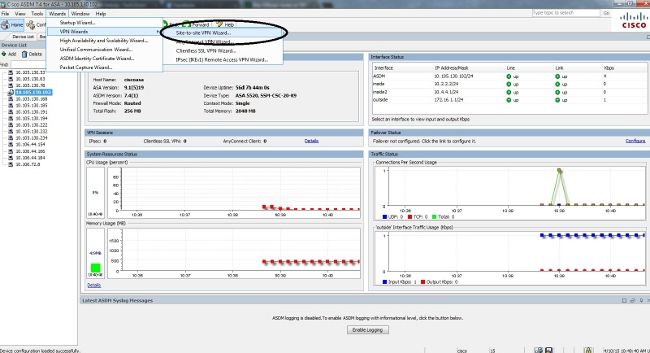
- Open the ASDM and navigate to Wizards > VPN Wizards > Site-to-site VPN Wizard:
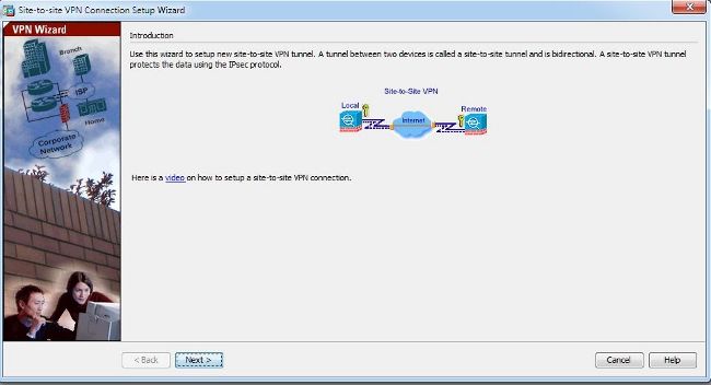
- Click Next once you reach the wizard home page:
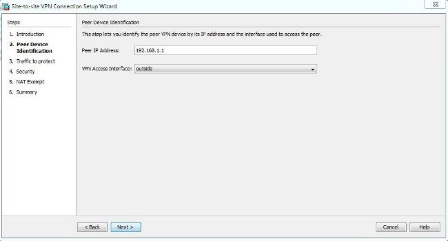
- Configure the peer IP address. In this example, the peer IP address is set to 192.168.1.1 on Site B. If you configure the peer IP address on Site A, it must be changed to 172.16.1.1. The interface through which the remote end can be reached is also specified. Click Next once complete.
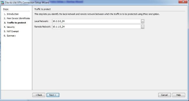
- Configure the local and remote networks (traffic source and destination). This image shows the configuration for Site B (the reverse applies for Site A):
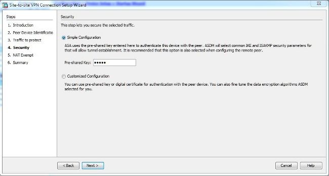
- On the Security page, configure the pre-shared key (it must match on both of the ends). Click Next once complete.
- Configure the source interface for the traffic on the ASA. The ASDM automatically creates the Network Address Translation (NAT) rule based on the ASA version and pushes it with the rest of the configuration in the final step.

- Enter this command into the CLI in order to enable IKEv1 on the outside interface:
crypto ikev1 enable outside - Create an IKEv1 policy that defines the algorithms/methods to be used for hashing, authentication, Diffie-Hellman group, lifetime, and encryption:
crypto ikev1 policy 1
!The 1 in the above command refers to the Policy suite priority
 (1 highest, 65535 lowest)
  authentication pre-share
  encryption aes
  hash sha
  group 2
  lifetime 86400
- Create a tunnel group under the IPsec attributes and configure the peer IP address and the tunnel pre-shared key:
tunnel-group 192.168.1.1 type ipsec-l2l
tunnel-group 192.168.1.1 ipsec-attributes
 ikev1 pre-shared-key cisco
!Note the IKEv1 keyword at the beginning of the pre-shared-key command
- Create an access list that defines the traffic to be encrypted and tunneled. In this example, the traffic of interest is the traffic from the tunnel that is sourced from the 10.2.2.0 subnet to the 10.1.1.0. It can contain multiple entries if there are multiple subnets involved between the sites.
In Versions 8.4 and later, objects or object groups can be created that serve as containers for the networks, subnets, host IP addresses, or multiple objects. Create two objects that have the local and remote subnets and use them for both the crypto Access Control List (ACL) and the NAT statements.object network 10.2.2.0 subnet 10.2.2.0 255.255.255.0 object network 10.1.1.0 subnet 10.1.1.0 255.255.255.0 access-list 100 extended permit ip object 10.2.2.0 object 10.1.1.0
- Configure the Transform Set (TS), which must involve the keyword IKEv1. An identical TS must be created on the remote end as well.
crypto ipsec ikev1 transform-set myset esp-aes esp-sha-hmac
- Configure the crypto map, which contains these components:
- The peer IP address
- The defined access list that contains the traffic of interest
- The TS
- An optional Perfect Forward Secrecy (PFS) setting, which creates a new pair of Diffie-Hellman keys that are used in order to protect the data (both sides must be PFS-enabled before Phase 2 comes up)
- Apply the crypto map on the outside interface:
crypto map outside_map 20 match address 100
crypto map outside_map 20 set peer 192.168.1.1
crypto map outside_map 20 set ikev1 transform-set myset
crypto map outside_map 20 set pfs
crypto map outside_map interface outside
The wizard now provides a summary of the configuration that will be pushed to the ASA. Review and verify the configuration settings, and then click Finish.
Configure Via the CLI
Phase 1 (IKEv1)
Complete these steps for the Phase 1 configuration:
Phase 2 (IPsec)
Complete these steps for the Phase 2 configuration:
NAT Exemption
Ensure that the VPN traffic is not subjected to any other NAT rule. This is the NAT rule that is used:
nat (inside,outside) 1 source static 10.2.2.0 10.2.2.0 destination static 10.1.1.0 10.1.1.0 no-proxy-arp route-lookup
object-group network 10.x.x.x_SOURCE network-object 10.4.4.0 255.255.255.0 network-object 10.2.2.0 255.255.255.0 object network 10.x.x.x_DESTINATION network-object 10.3.3.0 255.255.255.0 network-object 10.1.1.0 255.255.255.0 nat (inside,outside) 1 source static 10.x.x.x_SOURCE 10.x.x.x_SOURCE destinationComplete Sample ConfigurationHere is the complete configuration for Site B:crypto ikev1 enable outside crypto ikev1 policy 10 authentication pre-share encryption aes hash sha group 2 lifetime 86400 tunnel-group 192.168.1.1 type ipsec-l2l tunnel-group 192.168.1.1 ipsec-attributes ikev1 pre-shared-key cisco !Note the IKEv1 keyword at the beginning of the pre-shared-key command. object network 10.2.2.0 subnet 10.2.2.0 255.255.255.0 object network 10.1.1.0 subnet 10.1.1.0 255.255.255.0 access-list 100 extended permit ip object 10.2.2.0 object 10.1.1.0 crypto ipsec ikev1 transform-set myset esp-aes esp-sha-hmac crypto map outside_map 20 match address 100 crypto map outside_map 20 set peer 192.168.1.1 crypto map outside_map 20 set ikev1 transform-set myset crypto map outside_map 20 set pfs crypto map outside_map interface outside nat (inside,outside) 1 source static 10.2.2.0 10.2.2.0 destination static 10.1.1.0 10.1.1.0 no-proxy-arp route-lookup static 10.x.x.x_DESTINATION 10.x.x.x_DESTINATION no-proxy-arp route-lookup